

Due to the complexity of the Operational Technology (OT) environment and the frequent lack of documentation about the network’s status, this report aims to offer a clear overview of the current state of OT networks, the most commonly used protocols and their issues, as well as the most effective approaches for monitoring these types of infrastructures
When we talk about OT environments, we usually picture a set of production machines connected to PLCs (Programmable Logic Controllers), SCADAs (Supervisory Control and Data Acquisition), DCSs (Distributed Control Systems), CNCs (Computer Numerical Control), and other control systems that manage various industrial processes using protocols that are often proprietary — meaning they are subject to intellectual/industrial property rights. Adding to this the wide variety of vendors and protocols, it becomes clear that monitoring these networks poses a significant challenge.
Standards like OPC UA or BACnet have emerged to promote interoperability. However, many modern solutions no longer rely strictly on protocols to deliver effective monitoring.
The introduction of Industry 4.0 has led to a shift toward TCP/IP-based protocols such as Modbus TCP, S7comm, and Profinet, opening new possibilities for monitoring, even without adopting a unified standard protocol.
This article is organized into seven sections in addition to this introduction:
- Section 2: Relationship between IT and OT environments
- Section 3: Typical industrial network architecture
- Section 4: Industrial communication protocols
- Section 5: Log collection
- Section 6: OT traffic analysis
- Section 7: Conclusions
A typical OT network VS. reality
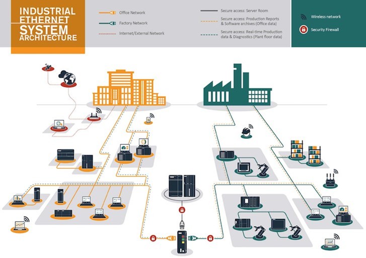
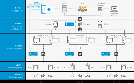
In theory, IT and OT networks are expected to be completely segregated, as illustrated in Figure 1. However, the reality is quite different: these environments are increasingly integrated, blurring the line between them.
The introduction of IT technologies into OT environments has brought new threats that industrial equipment is often unprepared for, since they were originally designed with priorities like availability and stability in mind.
This has created an urgent need for continuous protection and monitoring within OT environments.
Industrial network architecture
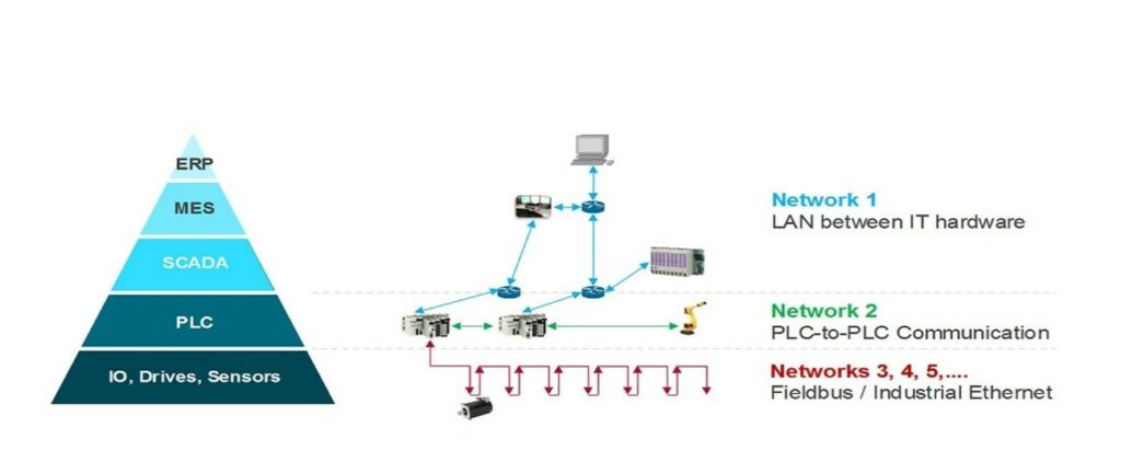
OT architecture typically starts with PLCs, which function as the brain of the network. From there, they connect “northbound” to SCADA systems, IT servers, and management interfaces (climbing the Purdue Model), and “southbound” to sensors, actuators, and other industrial machinery (descending the Purdue Model).
As shown in Figure 2, an industrial network can have multiple subnets using different communication protocols and models. It’s also common to find machine-to-machine communication (e.g., between PLCs) without routing through switches or routers
PLC’s and protocols
While PLC manufacturers (Siemens, Schneider, Allen-Bradley, etc.) generally offer similar functionalities, they differ in the communication protocols they support.
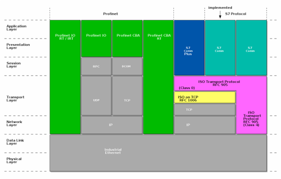
Some protocols are open and well documented, while others are proprietary, which complicates their analysis. An example is S7comm and S7comm Plus, used by Siemens equipment.
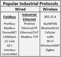
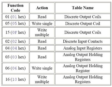
Figure 3 shows the most commonly used industrial protocols. These protocols vary in compatibility and openness, which impacts how easily they can be monitored.
Log collection
The first logical step in monitoring an OT network is collecting logs from the machines. In some environments, this is done using “Historians”, which store process data in time series.
However, especially in small and medium-sized enterprises (SMEs), these systems are uncommon due to cost and the lack of technological updates toward Industry 4.0 standards.
Additionally:
- PLCs don’t store logs by default unless specifically programmed to do so.
- Collecting logs directly from PLCs requires modifying each one individually, which is often not feasible.
For this reason, many commercial solutions don’t collect logs directly but instead monitor network traffic, identifying patterns and events directly from it.
An effective strategy is to connect these systems to TAPs or switch mirror ports, allowing them to listen to all traffic between industrial devices.
This approach allows monitoring northbound traffic to/from PLCs, but typically not southbound traffic to sensors and controllers. It is a non-intrusive and widely used technique in modern OT projects.
Traffic analysis
Industrial protocols can be classified into two broad groups: TCP/IP-based (e.g., Modbus TCP, S7comm) and non-TCP/IP-based (e.g., Profibus, CAN).
As many modern industrial networks migrate toward IP, we focus on three relevant protocols:
- Modbus TCP (open)
- S7comm (proprietary)
- S7comm Plus (proprietary and encrypted)
A. MODBUS TCP
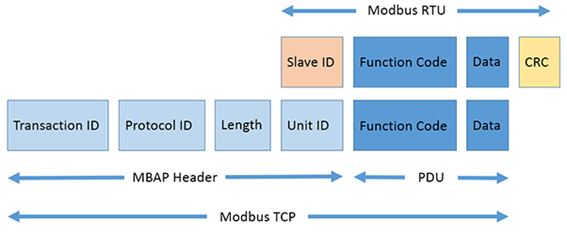
Modbus is a serial communication protocol created in 1979 for industrial environments. It is open and widely adopted in both serial (Modbus RTU/ASCII) and Ethernet (Modbus TCP) versions.
It operates under a master-slave (or client-server) model, where the master/client requests data or commands, and the slave/server (up to 247 devices) responds or executes instructions.
Common uses:
- Connecting field devices and sensors with SCADA systems.
- Transmitting temperature, pressure, level signals, etc.
1) Simulation Environment
We used open-source tools to simulate Modbus:
- ModbusPal: A graphical, scriptable multi-slave simulator.
- Mbtget: A Perl script to make console-based Modbus requests, supporting TCP and RTU.
2) Results
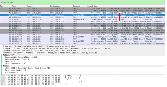
As shown in Figure 7, we successfully simulated Modbus traffic using ModbusPal. Packets displayed fields like transaction ID, function code, slave address, and data (registers or bits). Since everything is open, monitoring is straightforward. However, due to its lack of encryption, Modbus poses a security risk if not properly isolated or protected.
B. S7comm
S7comm is a proprietary protocol used by Siemens PLCs. There is no complete official documentation (not even consistent terminology), but projects and libraries like Snap7 and a Wireshark dissector aid in analysis.
S7comm protocols are generally divided into two families:
- S7comm clásico: still widely used.
- S7comm Plus: encrypted and poorly documented.
Typical Scenario:
A PC station communicates with a PLC using the S7 protocol (e.g., to load programs, read memory, or monitor states). It uses a client-server model: the PC is the client, the PLC the server.
The protocol is encapsulated in ISO-COTP over TCP, using TPKT as a wrapper.
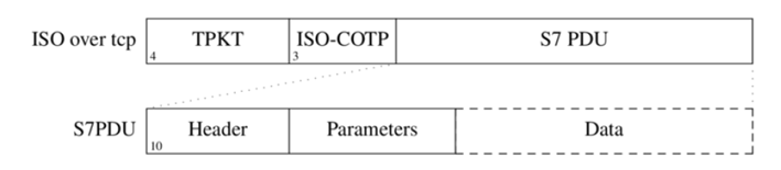
The packet includes:
- Header (length, message type)
- Parameters (varies by function type)
- Data (memory, firmware, etc.)
C. S7comm PLUS
Unlike classic S7comm, S7comm Plus is encrypted, making it unanalysable with traditional tools. Some Wireshark dissectors have been developed, but real-world tests have shown limited success.
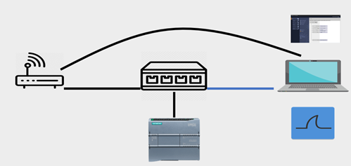
- Test Environment
We set up:
- A Siemens S7-1200 PLC
- A PC with TIA Portal v15
- A switch with a mirror port
- Wireshark + S7comm Plus plugin
Scenarios executed:
- Connect/disconnect TIA Portal to PLC
- Upload/download configurations
- Set PLC to “RUN” or “STOP” mode
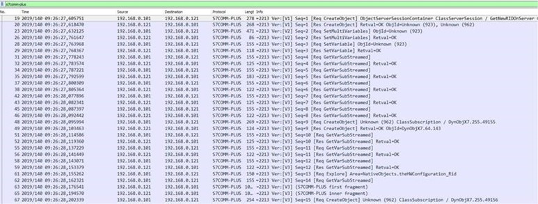
2) Results
The Wireshark plugin failed to properly decrypt or interpret packets. Traffic appeared encrypted, and no official documentation exists to decipher it.
Analysis Conclusions:
- Classic S7comm is understandable and useful for monitoring.
- S7comm Plus is a “black box” from a cybersecurity perspective.
- Alternative strategies (behavior or anomaly-based detection) are needed for encrypted protocols.
Conclusions
OT environments are far more complex to scan and monitor than IT environments due to the diversity of protocols, vendors, and architectures.
While some protocols are well documented, others, like S7comm Plus, remain closed off, limiting visibility.
The current trend in OT monitoring solutions is to focus on the IP layer, enabling visibility regardless of the underlying protocol.
Recommendations:
- Use network traffic as the primary log source.
- Incorporate behavior and anomaly detection.
- Prioritize passive solutions to avoid operational disruptions.
Ready to gain real visibility into your OT network?
At InprOTech, we help you identify risks, analyze industrial protocols, and monitor your OT infrastructure without compromising the operational continuity of your industrial environment.
If you found this article useful or are looking to gain real insight into your OT network, don’t hesitate to contact us here or visit our InprOTech Guardian page and specialized services to learn how we can support you.
Our industrial cybersecurity experts are ready to guide you toward a safer, more efficient, and more resilient OT network.