


The S7 Communication protocol (hereafter S7Comm) is a Siemens proprietary protocol that first appeared in 1994 with the launch of Simatic S7 products such as S7-200, S7-300 and S7-400, although it is currently integrated by all SIMATIC S7 and C7 CPU devices and is independent of the bus used, as this protocol can be used both through Industrial Ethernet and through other physical or network layers such as over RS-485 for MPI (Multi-Point-Interface) or Profibus [1].
This protocol is mainly used for data exchange, as well as for access from other devices such as HMI or SCADA.
As this is a proprietary protocol, there is not much information publicly available about it, although there are several projects that can help to understand it, such as Snap7 [2], which is an open source library that can be used to interact with Siemens S7 products and includes extensive technical documentation on the operation of this protocol.
Another large open source project that includes information on this S7 protocol is PLC4X [3], which includes a set of libraries to implement communication between PLCs with different industrial protocols through its API, including S7.
When we talk about the S7Comm protocol, we could really be referring to both S7Comm and its most recent version, S7Comm Plus, of which there is very little information and which includes, as a new feature, an encryption layer. Throughout this article, we will only talk about the S7Comm protocol, which is mainly used for connections between PLCs and PC stations.
Technical description
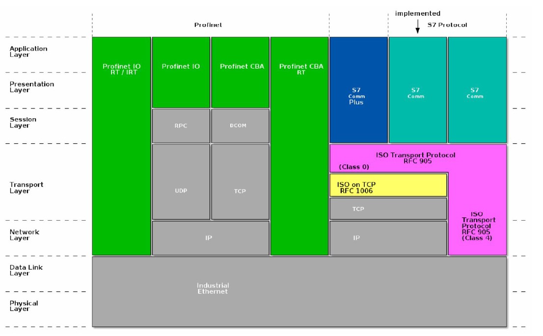
Generally, the communication designed by Siemens follows the traditional master-slave (or client-server) model. where a master (or client) PC sends S7 requests to the slave (or server) PLC device).
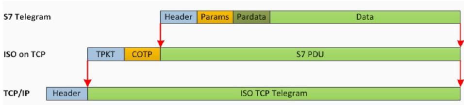
The implementation of the S7 protocol over TCP/IP is based on the blockoriented ISO transport service. This protocol is encapsulated in the TPKT and ISO-COTP protocols, allowing the transfer of the PDU (Protocol Data Unit) via TCP, using by default TCP/102 port for communications.
Each of the data blocks that are transmitted are so-called PDUs, the length of which is negotiated during connection setup.
The protocol is function and/or command oriented, which means that the transmission generally consists of an S7 request and a response to that request. Each of these commands consists of the following commands fields, the last two being optional:
- Header
- Parameter set (and parameter
- data)
- Data
For a better understanding of S7 encapsulation, the following picture shows how S7 is first encapsulated in ISO over TCP and then in TCP/IP:
HEADER: contains PDU length and identification information, and message type constant.
These headers are between 10 and 12 bytes long; ACK messages contain two additional bytes of error code. Apart from this, the header format is always the same in all PDUs.
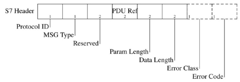
Protocol ID: Protocol identifier. It is constant, it will always be 0x32.
Message Type: Type of the message; sometimes referred to as ROSCTR (Remote Operating Service Control) 0x01-Job Request: Request sent by the master (e.g. read/write memory, read/write blocks, start/stop device, setup communication)
- 0x02-Ack: Simple ACK sent by the slave without data field.
- 0x03-Ack-Data: ACK with optional data field, contains the response to a job request.
- 0x07-Userdata: An extension of the original protocol; the parameter field contains the request/response ID. Used for e.g. scheduling or debugging tasks, SZL reads, security functions, time settings, cyclic reads, etc.)
Reserved: Always 0x0000 (ignored).
PDU reference: Generated by the master; it is incremented with each new transmission and is used to link the responses with their requests, i.e. for frame traceability, Little-Endian.
Parameter length: The size of the parameter field, Big Endian.
Data length: The size of the data field, Big-Endian.
Error class: Only present in Ack-Data messages.
Error Code: Only present in Ack-Data messages.
PARAMETERS AND DATA: The parameter header is specific to the message type and for Job and Ack Data messages shall start with a function code. The structure of the rest of the fields depends on this value. This function code determines the purpose of the message and serves as a basis for the message exchanges that will take place.
Functions
Setup Communication
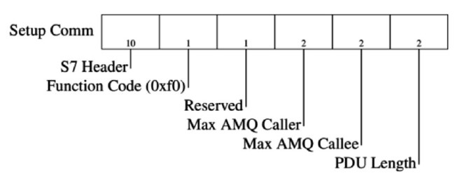
Before any message can be exchanged, client and server (master and slave) exchange the Job and ACK Data message pair at the beginning of each session. Their function is to negotiate the size of the ACK queue and the maximum length of the PDU. The ACK queue length determines the number of parallel Jobs that can be started simultaneously without acknowledgement. Both the ACK queue length and PDU length fields are Big Endian.
Read/Write Variable [0x04/0x05]
The S7 protocol supports multiple variable read/write queries in a single message with different addressing modes. There are three main modes:
Any-type: This is the default addressing mode and is used for variable queries arbitrary. The three parameters (area, address, type) are specified for each addressed variable
Db-type: This is a special mode designed to address database variables. It is more compact.
Than any-type addressing.
Symbolic-addressing: This mode is used by the S7-1200/1500 series devices and allows the addressing of certain variables with their predefined symbolic names. This mode is rare.
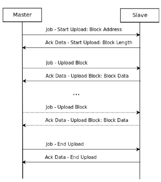
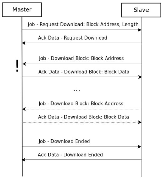
Block Upload/Download [0x1a-1f]
In Siemens devices, the program code and most of the program data are stored in blocks. These blocks have their own header and encoding format, which can be found in more detail in the official Siemens documentation. [4]
The message exchange sequence can be either upload block or download block. The main difference between the two is that in download block, the direction of communication changes and “the slave becomes the master”, i.e. it is the slave that sends the data to the master.
PLC Control [0x28]
PLC Control messages are used to execute different routines on the slave device that modify its execution/memory state. These commands are used to start or stop the execution of the PLC control program, activate or delete program blocks in the device or save its configuration in persistent memory.
PLC Stop [0x29]
The PLC Stop message is essentially the same as the PLC control message with the difference that the message has no parameters and the routine part is always set to P_PROGRAM.
MSG Type – Userdata [5]
In cases where the message type field is 0x07-Userdata, the format of the frame containing the parameter field and data field changes with respect to cases where a Job request or Ack data is sent. The fields are as follows:
Parameters:
- Parameter Head
-
- Parameter length: longitud del campo parámetros
- Method: Request/Response(0x11/0x12)
- Type: Request (4)/Response(8)
- Function Group:
- Programmer commands
- Cyclic data
- Block functions
- CPU functions
- Security
- Time functions
- Subfunction: dependen del valor del campo “Function Group”; para el caso de CPU Functions:
- Read SZL
- Message service
- Transition to stop
- Alarm was acknowledged in HMI/SCADA 1
- Alarm was acknowledged in HMI/SCADA 2
- PLC is indicating a ALARM message
- HMI/SCADA initiating ALARM subscription
- Sequence number
- Data unit reference number: (only for responsive)
- Last data unit: (solo para Response)
- Yes (0x00)
- No (0x01)
- Error code: (solo para Response)
- Datos
- Return code:
- 0x00 – Reserved
- 0x01 – Hardware fault
- 0x03 – Accessing the object not allowed
- 0x05 – Address out of range
- 0x06 – Data type not supported
- 0x07 – Data type inconsistent
- 0x0a – Object does not exist
- 0xff – Success
- Transport size:
- 0x00 – NULL
- 0x03 – BIT
- 0x04 – BYTE/WORD/DWORD
- 0x05 – INTEGER
- 0x07 – REAL
- 0x09 – OCTET STRING
- Length
- SZL-ID
- SZL-Index: With certain partial lists or extracts from partial lists an object type ID or object number must be specified.
- Length of a data record of the partial list in bytes: (Response only)
- Number of data records contained in the partial list: (for Response only)
SZL-ID
SZLs or SSLs (System Status Lists) are lists describing the current status of a PLC, the contents of which can be read, but not changed.
These lists are virtual lists that are created by the CPU operating system when requested [5]. The information that can be extracted through these SSLs is the following:
- System data
- CPU configuration
- Priority class status
- Communication
- Status data of CPU modules
- Module diagnostic data
- Diagnostic buffer
Analysing the fields contained within the SZLs, we find the following:
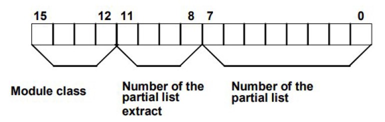
Consisting of three main fields::
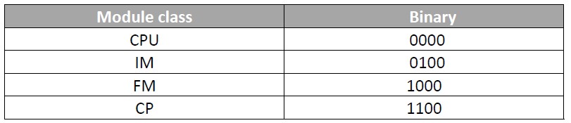
- Module class (4 bits)
- Number of the partial list extract (4 bits): The number of partial list extracts and their meaning depend on the particular system status list to which they belong. With the number of the partial list extract, you specify which subset of a partial list you want to read.
- Number of the partial list (8 bits): Using the partial list number, specifies which partial list of the system status list is to be read.
- SZL-Index: With certain partial lists or extracts from partial lists an ID of type must be specified
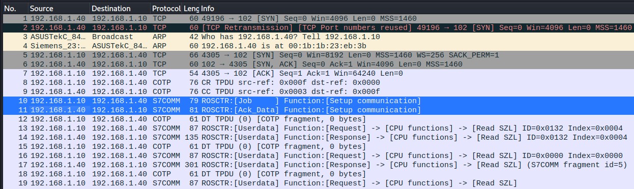
As can be seen in Figure 8, packets 10 and 11, the first thing that is done before exchanging messages via S7 is to exchange the Job and ACK Data message pair to set the size of the ACK queue and the maximum length of the PDU.
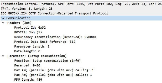
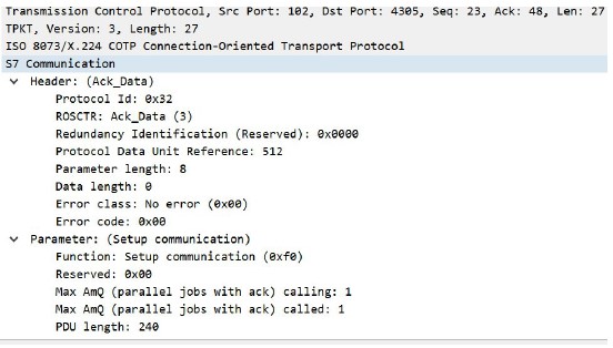
You can see in the images above the parameters described above for the Setup Communication function, such as Protocol ID=0x32, and the Job (0x01) and Ack_Data (0x03) functions.
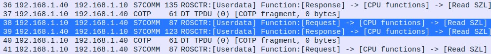
After the connection is established, Request – Response functions start to be exchanged with an MSG Type
0x07 Userdata, through which the client performs “Read SZL” or System Status List functions. Based on what was discussed in the previous chapter about how SSLs (or SZLs) work, it is possible to deduce which operations are being performed on the selected capture and extract information from it. In addition, Wireshark itself identifies which operation corresponds to each of the SSL-IDs:
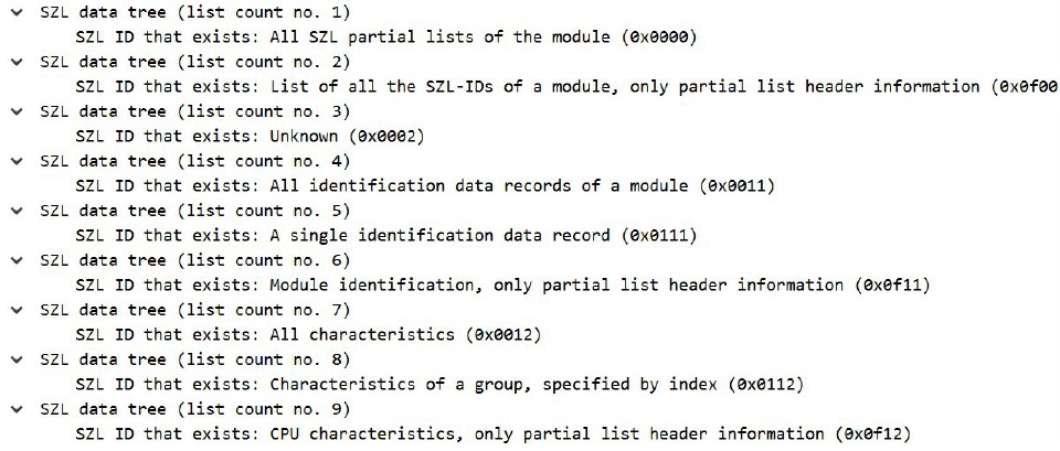
In packet 17 (Figure 8), the client sends an SZL-ID (SSL-ID)=0x0000, so all the IDs of the lists available to the PLC are obtained:
SZL-ID: 0x0000, Diagnostic type: CPU, Number of the partial list extract: All SZL partial lists of the module, Number of the partial list: List of all the SZL-IDs of a module.
Below is a sample of the lists returned by the server:
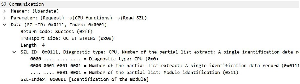
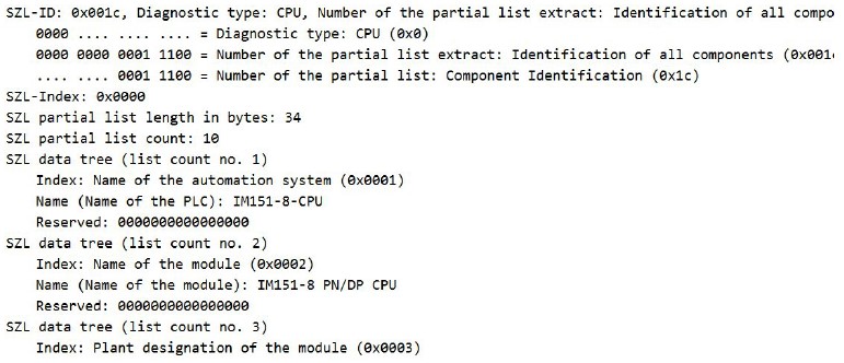
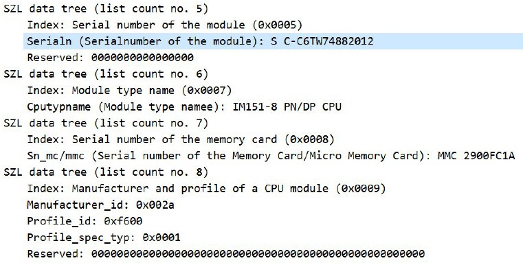
From here you can extract important information as you can see below; after the previous query of all existing SSLIDs, one of them is SSL-ID=0x111, which corresponds to Diagnostic type: CPU, Number of the partial list extract: A single identification data record, Number of the partial list: Module identification.
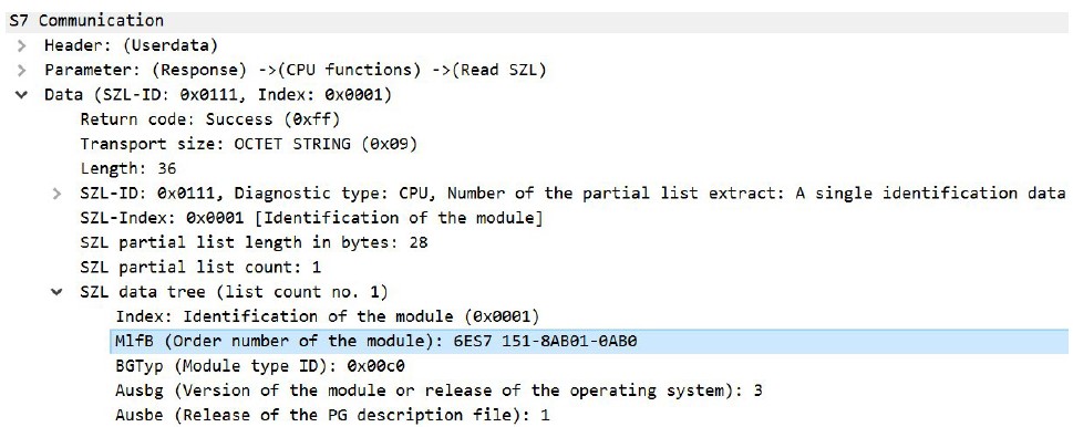
As can be seen in the two figures above, the slave returns hardware information: 6ES7151-8AB01-0AB0. If you do a quick Google search, you can find out which specific device is communicating, as it also returns the OS version value (3). According to the search, the device involved is the following: SIMATIC DP, IM151-8 PN/DP CPU for ET 200S, 192 KB working memory, PROFINET int. interface (with three RJ45 ports) as IO controller, no battery MMC required. [7]
It can be seen from Figure 16 that the module name is indeed IM151-8 PN/DP CPU.
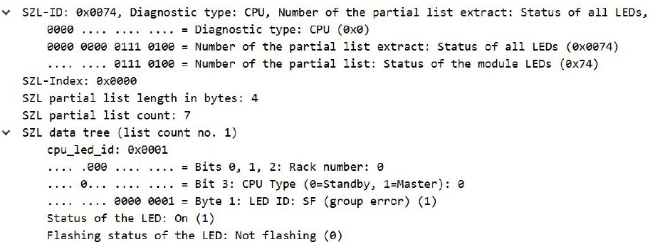
The status of the system’s LEDs is also read out:
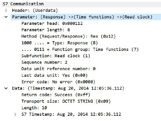
In addition, it has been possible to read the internal clocks of the system:
You can even read an extract from the device’s diagnostic logs:
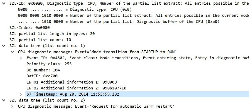
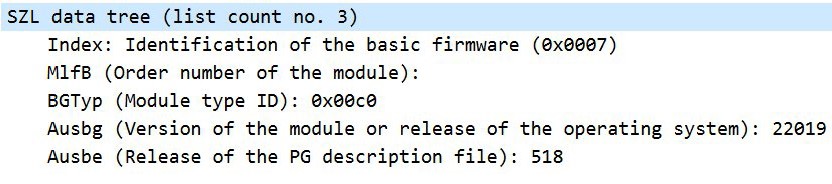
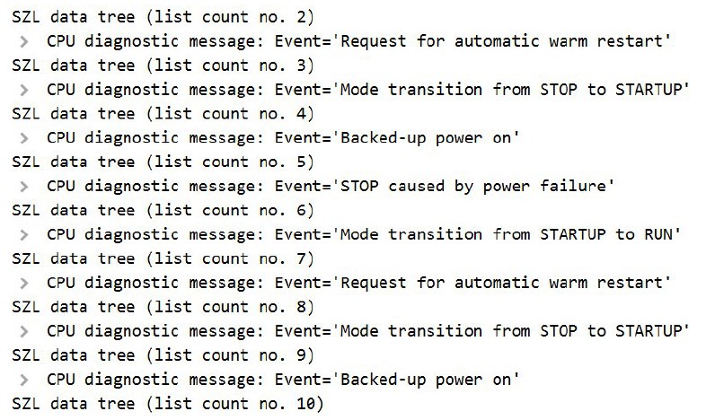
Furthermore, as can be seen in Figure 20, through the SZL-ID=0x00a0 it is even possible to extract the existing entries in the diagnostic buffer and read each one of them; in this particular case, it can be seen that on 20 August 2014 at 11:53, an event “Mode transition from STARTUP to RUN” was generated. The following figure includes more existing events in the buffer:
Conclusions
Although the latest version of the S7 protocol (S7 Comm Plus) has encryption and authentication mechanisms,
Its use is not yet widespread and it is still common to find the S7-ISOonTCP protocol (S7 which has been the subject of analysis in this article).
As could be seen in the analysis of the capture, the information exchanged between master and slave is in plain text so that all the information sent between the two can be captured.
This protocol, as it does not have authentication, allows an attacker who has access to the network where the master and slave (PC and PLC) are located, to sniff network traffic and obtain valuable information from the PLC so that, once the IP address of the PLC and the model and/or firmware version have been identified, a search for vulnerabilities that could affect this device can be carried out.
In addition, Siemens devices by default use tcp port 102 to run their services, so you could also use an nmap query targeting only port 102 on an entire network to get information about devices that may be behind this port.
Referencias
[1] https://support.industry.siemens.com/cs/document/26483647/what-properties-advantages-and-special-features-does-the-s7-protocoloffer-?dti=0&lc=en-WW
[2] http://snap7.sourceforge.net/
[3] https://plc4x.incubator.apache.org/protocols/s7/index.html
[5] System Software for S7-300/400 System and Standard Functions Volume ½, https://readthedocs.web.cern.ch/download/attachments/21177680/SIEMENS%20S7%20-%20SZL%20addresses%20guide.pdf?version=1&modificationDate=1403874207000&api=v2
[6] https://wiki.wireshark.org/SampleCaptures#s7comm-s7-communication
[7] https://mall.industry.siemens.com/mall/es/es/Catalog/Product/6ES7151-8AB01-0AB0