


Have you ever needed to simulate or intercept Modbus communications to debug or automate processes? In this article, we show you how to do it safely and effectively.
Modbus is the de facto standard communication protocol for the industrial world. It was initially designed to be used in serial communications (Modbus RTU/ASCII). However, not long ago, it was adapted to TCP due to the increasing popularity of the TCP/IP stack.
Since it was originally designed for controlled serial lines, Modbus does not have any security features. In this paper, we wrote several benchmarks to evaluate the performance of networking devices that run Modbus TCP.
Parameters reported by our benchmarks include: (1) response time for Modbus requests, (2) maximum number of requests successfully handled by Modbus devices in a specific amount of time, and (3) monitoring of Modbus devices when suffering a Distributed Denial of Service attack. Due to the growing adoption of IoT technologies, we present in this paper the modbus protocol and selected various tools to manipulate it.
Introduction
hen dealing with ICS networks, Modbus is the most used protocol in the different industries. The reason behind it’s excessive use is that it was introduced to the market more than 30 years ago, and due to the industry limits of change over the past years, most of the industrial network is still using this protocol. This Serial communication protocol invented in 1979 by Schneider Electric and, developed for industrial application and Royalty-free considered as one of the standards for industrial communications.
In this work we start by presenting ICS basic knowledge and architecture. In chapter 2 we presented Modbus as an ICS network standard protocol. Then in chapter 3 we explained how to analyze the Modbus traffic. In chapter 4, we presented several tools to simulate and exploit the modbus traffic . Finally, we conclude this paper with our intake on this work.
ICS
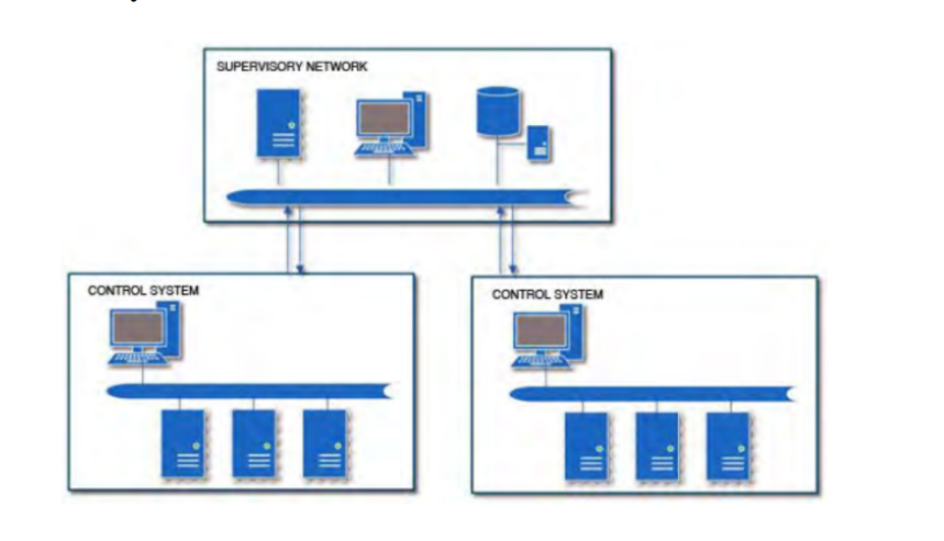
Industrial Control Systems (ICS) are devices, systems, networks, and controls used to operate and/or automate industrial processes. These devices are often found in nearly any industry—from the vehicle manufacturing and transportation segment to the energy and water treatment segment. Supervisory Control and Data Acquisition (SCADA) networks are systems and/or networks that communicate with ICS to provide data to operators for supervisory purposes as well as control capabilities for process management. As automation continues to evolve and becomes more important worldwide, the use of ICS/SCADA systems is going to become even more prevalent.
ICS/SCADA systems have been the talk of the security community in the recent years due to Stuxnet, Flame, and several other threats and attacks. While the importance and lack of security surrounding ICS/SCADA systems is welldocumented and widely known, this research paper illustrates who’s really attacking Internet-facing ICS/SCADA systems and why. It also covers techniques to secure ICS/SCADA systems and some best practices to do so. A typical deployment often has a segregated SCADA network that is either connected via a firewall or air-gapped from the Internet. As in most ICS deployments, firewalls are a rarity, so please keep in mind that a firewall is not shown in the following diagram for this reason. There was also no mention of firewalls throughout the analysis.
MODBUS
Modbus is an application layer messaging protocol, positioned at level 7 of the OSI model that provides Master/Slave communication between devices. Modbus protocol is used for transmitting information over serial lines between electronic devices. The device requesting the information is called the Modbus Master and the devices supplying information are Modbus Slaves.
In a standard Modbus network, there is one Master and up to 247 Slaves, each with a unique Slave Address from 1 to 247. The Master can also write information to the Slaves. Modbus is a request/reply protocol (Devanshi N. Patel, 2017). Modbus function codes are elements of Modbus request/reply Protocol Data Units (PDU). At the physical level, Modbus may use different physical interfaces like RS485, RS232. RS485 two-wire interface is the most common. RS232 serial interface is used for short distance communication while RS485 serial interface is used for long distance communication. The packet format of Modbus can be seen in the following table .
A Modbus message sent from a master to a slave contains the address of the slave, function code and data.
Slave address
Every slave has its unique Unit Address from 1 to 255. When the master requests data. The slave address is of 1-byte. In this system, two slaves are used and the slave address of these slaves are set as ‘UI2’ and ‘UI4’.
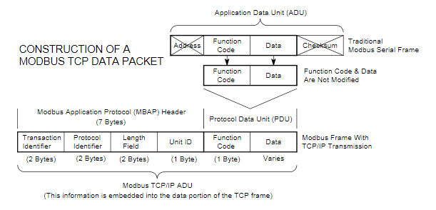
Function code
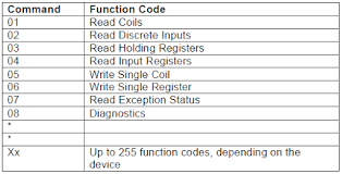
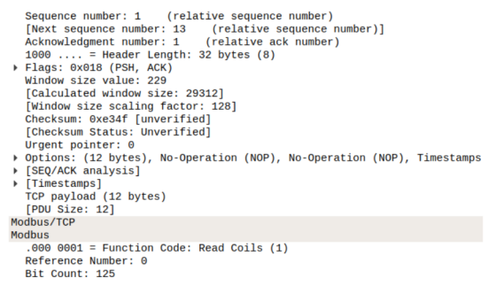
This code tells the slave which table to access and whether to read from or write to the table. In this system, read and write functions are used and the function code for read is ‘01’ for coil and ‘03’ for register. Function code for write is ‘06’. The most common Modbus functions allow reading and writing data from/to a PLC. Other functions, such as file read and diagnostics functions also exist. Undocumented Modbus function codes can also be used to perform specific actions. The following table shows the most commonly used function.
Data
Data must be user defined. It is up to 0 to 252 bytes.
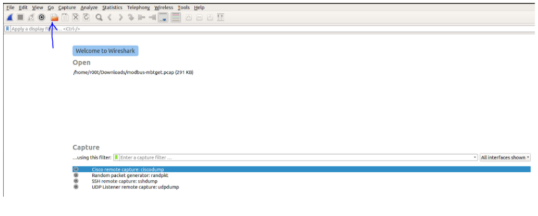
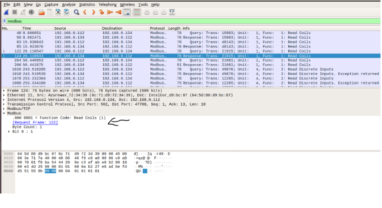
Using modbus with wireshark
In order to use Wireshark on a Modbus traffic, we need to first collect Modbus traffic using a network sniffer. Modbus PCAPs can be easily found online. When having a Modbus PCAP file:
- We start wireshark.
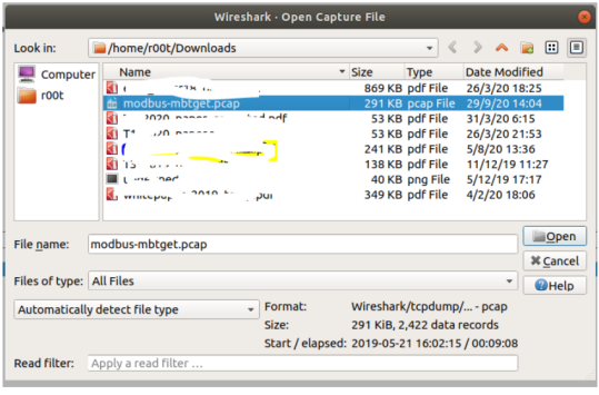
- Click on the open a capture file
- Select the PCAP file
- In the filter field write “modbus”
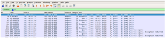
- You can directly see the function for example and more information related to the selected transactions.
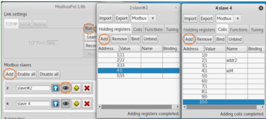
Using modbuspal as a modbus slave simulator
After downloading the ModbusPal source, we first run the ModbusPal on a Linux VM1. The command to run the ModbusPal Java code is:
#java – jarModbusP al.jar
- When the program starts, click the ”Add” button to manually add two Slaves (ID: 2 and 4).
- Click the ’eye’ icon on a Slave bar to open the Slave panel and edit its content.
- In each Slave panel, add holding registers (16-bit) and coils (bit), and change some of their values. (Note that the coil only has a value of 0 or 1).
- Then click the ”Run” button on ModbusPal to run the simulator, which will listen and accept incoming TCP connections to port 502.
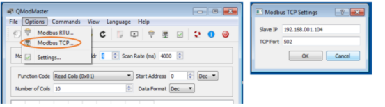
Using qmodmaster as a modbus master simulator
- Start the QModMaster Simulator on a Windows VM2 .
- Edit the ”Modbus TCP…” under the ”Options” menu, and put the ModbusPal’s IP address (VM1).
- Click the ”Connect” button to let Master set up TCP port 502 connection to ModbusPal.
- Now the Master is ready to access/modify Slaves’ data.
Using qmodmaster and modbuspal
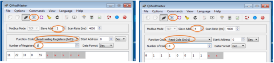
Read Slave’s Data
- QModMaster, change the ”Slave Addr” to be the Slave ID you want to query, select the ”Function Code” to read holding Slave’s registers or read coils, choose the ”Number of Registers/Coils” to be less than or equal to the number of registers/coils you have created on the Slave node.
- Click the ”Read/Write” menu button to read data.
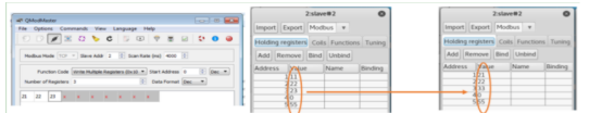
The following figure shows the Master obtains Slave 2’s registers data, and Slave 4’s coil data.
Modify Slave’s Data
Testing Modbus Master writing Registers/Coils data to Slaves.
- Change the function code to ”Write Multiple Registers”.
- Change the number of Registers to be less than or equal to the Slave’s predefined number of registers.
- Change those registers’ values,
- Click the ”Read/Write” command button, and you can see the register values on the corresponding ModbusPal Slave has been updated.
The following figure shows a change of multiple registers On QModMaster.
Using metasploit to modify modbus slaves
Because Modbus Master communicates with Slaves in plain-text and there is no authentication procedure, an attacker can easily generate the same format of query packets to Modbus Slaves to access/modify Slave’s registers/coils, as long as:
- The attacker’s machine can send packets to Modbus
Slave. - The packets sent by the attacker follow Modbus protocol format.
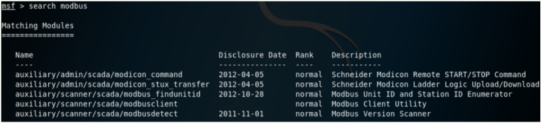
Hackers have incorporated Modbus attack modules in Metasploit, thus the second requirement above can be overcomed by using Metasploit. In Kali Linux, run ”msfconsole” to start Metasploit. When you search modbus, you can find the following attack modules:
In this experiment, we use a second Kali Linux VM (VM3: 192.168.1.103) to launch Metasploit attack. To satisfy the first requirement above, VM3 should be put in the same LAN as the target VM (VM1: 192.168.1.104) where ModbusPal is running.
Modbus Slave Scanner
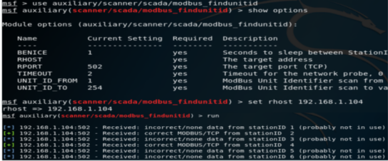
We can use the Metasploit ”modbus findunitid” attack module to scan and find out if all Modbus Slaves existed in the LAN or behind a Modbus Gateway. For the two Slaves created by ModbusPal shown on Figure 2, the Modbus Slave scan procedure is illustrated in the following figure. The only parameter to set is the ’rhost’ IP address (target IP), and we can see Slave ID 2 and 4 have been found.
Modbus Slave Data Access/Modify
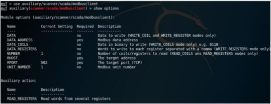
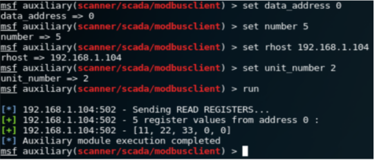
We can use the Metasploit ”modbusclient” [2] attack module to read/write registers/coils on a given Modbus Slave. The following test use the Modbus example shown in Figure 2. The default action for Modbusclient module is to read registers. The following figure shows how to read the 5 register values from Slave 2. Note that the ’data address’ 0 means the address 1 on ModbusPal GUI panel.
Now we change the ’action’ option to ”WRITE COILS” to write multiple coil values to Slave 4. The attack procedure is illustrated in the following figure. The 10 bits coil values can be seen updated on the Slave 4 on the target VM1.
Security Recommendations When Working with Modbus
Although Modbus is a widely used protocol in industrial environments due to its simplicity and efficiency, it’s important to keep in mind that it lacks built-in security mechanisms, such as authentication or encryption. This makes it particularly vulnerable if best practices are not followed.
Below are some key recommendations to keep Modbus environments more secure:
- Avoid exposing Modbus to public networks: Modbus devices should never be directly accessible from the Internet. If remote access is required, always use secure VPNs or encrypted tunnels to protect the communication.
- Network segmentation: Place Modbus devices within segmented networks or VLANs, separated from corporate or office traffic. This limits the scope of a potential attack.
- Traffic monitoring: Use tools like Wireshark or IDS/IPS systems to detect anomalous traffic on standard Modbus ports (such as 502/TCP). This helps identify unauthorized access or manipulation attempts.
- Physical access control: Since Modbus is also used over serial buses (Modbus RTU), it’s crucial to restrict physical access to the devices and RS-485 connections.
- Logging and auditing: Keeping a log of all connections and executed commands can help detect unexpected changes in device configuration or behavior.
Conclusion
In this paper we presented the Modbus protocol and several tools that can be used to analyze it in section, emulate it in section and exploit it in section.
If you found this topic interesting and would like to deepen your knowledge of Modbus or other industrial communication protocols, feel free to get in touch with our team here or explore our specialized training programs. At InprOTech, we’re always happy to help!